
![]()
- New programs
- New modules
- Code implementation and improvements in its application
- CYPECAD
- IFC Builder
- StruBIM Design
- CYPETHERM EPlus
- CYPETHERM EPlus and CYPETHERM LOADS
- CYPETHERM HVAC
- Arquimedes
- Return to the 2017 version download area
New programs
The following programs have been implemented in the 2017.b version. Each program requires its own user permits, and is installed when the installation is carried out in the language associated with the indicated country. More information is available on each program on the webpage of their corresponding language:
- CYPELUX RECS (Portugal)
- CYPETEL ITED (Portugal)
- CYPESOUND (International)
The program was already available in Spanish as of the 2017.a version. Now, as of the 2017.b version, the program can be installed in the remaining languages. - CYPESOUND RRAE (Portugal)
- CYPETHERM REH (Portugal)
- CYPETHERM IMPROVEMENTS (Portugal)
- CYPETHERM RTExistant (France)
New modules
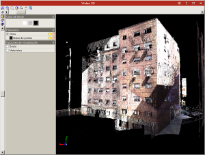
IFC Builder. Reading of point clouds (3DCONS project)
As of the 2017.b version, IFC Builder can read point clouds and take them as a reference for the development of existing buildings. This tool has been developed as part of the “New construction processes using 3D printing (3DCONS)” investigation project.
This module is included in IFC Builder and, like IFC Builder, is free to use.
More information on this tool can be found in the Reading of point clouds (3DCONS Project) section in the new features of the 2017.b version of IFC Builder.
Code implementation and improvements in its application
Loads on structures. Seismic loads
CFE 2015 (Mexico)
Manual de Diseño de Obras Civiles por Sismo México 2015.
Implemented in CYPECAD and CYPE 3D.
CYPECAD
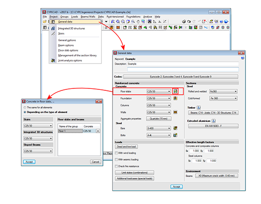
Concrete for floor slabs, stirs, integrated 3D structures and sloped beams
As of the 2017.b version, CYPECAD allows users to different types of concrete for the following elements:
- Floor slabs
For floor slabs, the type of concrete can be different for each floor group. - Stairs
- Integrated 3D structures
- Sloped beams
IFC Builder
Reading of point clouds (3DCONS project)
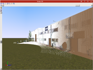
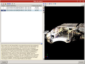
As of the 2017.b version, IFC Builder can read point clouds as a reference for the development of existing buildings.
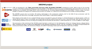
This module has been developed as part of the "New construction processes using 3D printing (3DCONS)" investigation project, which is part of the strategic program of the "National Business Research Consortia (CIEN)" of the Ministry of Economy and Competitiveness, financed by the "Centre for the Development of Industrial Technology (CDTI)", co-financed by the "European Regional Development Fund (ERDF)" and carried out by CYPE and the associates of the project: Atanga, Geocisa, Lafarge-Holcim, Placo, Proingesa and Vias; and the collaboration of the following investigation centres: CIM-UPC Foundation, the Eduardo Torroja Institute for Construction Science (CSIC), the University of Burgos, the CARTIF Technology Centre and the Polytechnic University of Madrid.
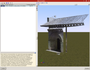
The 3DCONS project aims to introduce 3D printing technologies in the construction industry, both in the field of new construction and the rehabilitation and restoration of heritage, using point cloud technologies to read existing buildings. More information of the 3DCONS project.
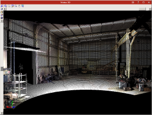
Point clouds are the result of one or several 3D laser scans composed of a group of vertices in a three-dimensional coordinate system, which are usually defined using X, Y and Z coordinates, and occasionally incorporate additional data such as colour using RGB values.
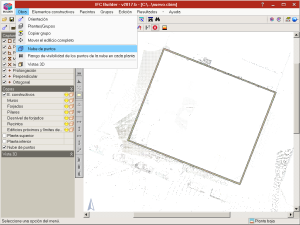
This way IFC Builder can provide a 3D or plan representation of point cloud files (*.pts; *.ptx; *.txt; *.xyz), which can be used as a support to model the real project in a precise and rapid manner from a BIM environment.
This module is included in IFC Builder, and, as IFC Builder, is also free to use.
StruBIM Design
Several tools have been added in the 2017.b version for improved use of the following program tools:
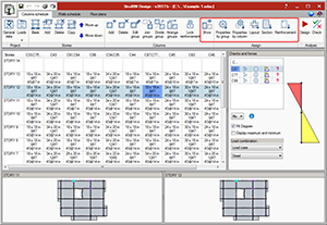
Column schedule
- Show/hide columns
- Select columns on floor plan view
- Options that can be assigned:
- Presence on plan
- Section
- Reinforcement
- Design properties
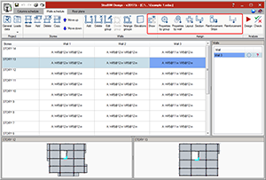
Wall schedule
- Show/hide walls
- Select walls on floor plan view
- Options that can be assigned:
- Presence on plan
- Section
- Reinforcement strips
- Reinforcement
- Design properties
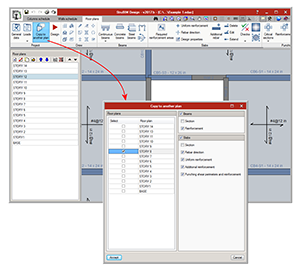
Floor plans
- Copy floors
Allows users to copy floor slab reinforcement, punching shear critical sections and reinforcement, frame reinforcement and sections from one floor to others.
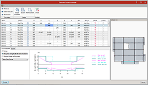
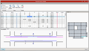
Concrete beam table
- Options to assign:
- Section
- Reinforcement
- Design properties
- Reinforcement diagram depending on the type of span
- Select beams on floor plan view
- Improved view of required reinforcement diagrams
Steel beam table
- Options to assign:
- Section
- Design properties
- Select beams on floor plan view
User manual, Calculations manual and videos
The user and calculations manuals of the free-access online version of StruBIM Design, as well as a series of demonstration videos of StruBIM have been edited. This information can be found in the following links:
- Strubim suite. General information
- StruBIM Design. User’s Manual
- StruBIM Design. General reference
- Watch and Learn
- StruBIM Suite (4:41)
- StruBIM Design. 1 NEW PROJECT (2:32)
- StruBIM Design. 2 COLUMN DESIGN (2:18)
- StruBIM Design. 3 WALL DESIGN (2:27)
- StruBIM Design. 4 SLAB DESIGN (2:13)
- StruBIM Design. 5 CONCRETE BEAM DESIGN (2:27)
- StruBIM Design. 6 PUNCHING SHEAR DESIGN (2:04)
- New project from Revit IFC file (5:08)
- StruBIM Design. New Features 2017 b (4:22)
- Features of StruBIM versions
CYPETHERM EPlus
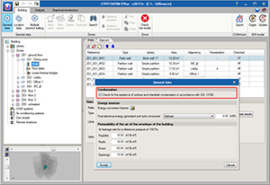
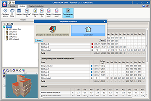
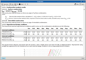
Surface and interstitial condensation check in accordance with ISO 13788
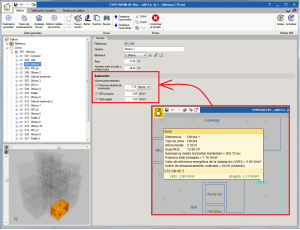
As of the 2017.b version, CYPETHERM EPlus incorporates a surface and interstitial condensation check in accordance with ISO 13788. This check was already available with CYPETHERM HYGRO.
The analysis is carried out automatically for all the construction elements of the thermal envelope if the check option is activated in the general parameters table. This way, the analysis carried out by CYPETHERM HYGO is perfectly integrated in both applications.
Upon checking the model of the building, CYPETHERM EPlus emits a warning if any condensation arises at any construction element, allowing users to view the results for each one and offering them a complete report of the analysis carried out on all the construction elements of the thermal envelope, organised in zones.
To activate this option, users must have the permits to use the Surface and interstitial condensation check in accordance with ISO 13788.
CYPETHERM EPlus and CYPETHERM LOADS
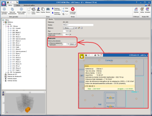
Integration of the lighting design results carried out in CYPELUX in Open BIM workflow
As of the 2017.b version, CYPETHERM EPlus and CYPETHERM LOADS allow users to import, using an IFC file, the results of the lighting analysis carried out in CYPELUX. This way, the programs can import the calculated installed lighting power in each precinct. Furthermore, users will be able to personalise this data in each precinct (only data in the type of precinct was available in previous versions).

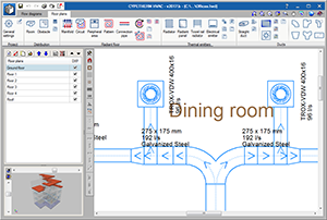
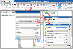
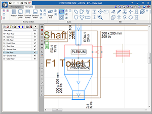
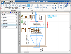
CYPETHERM HVAC
Design of duct networks
Pressure loss accumulated by networks
In the previous version (2017.a) the new feature to design air-duct networks using air flow drag from grilles to the initial span of the network was implemented.
Now, in the 2017.b version, the program detects the critical path to the worst-case grille and provides the value of the total pressure loss. The report displays the networks in order, with the spans that correspond to the critical path first. Furthermore, any connection elements used are displayed in the report (elbows, transformations and branches) with their associated pressure loss and in order of appearance.
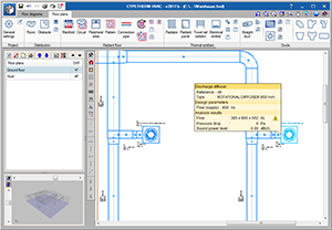
Flow range warnings
The program places a yellow warning triangle when a grille or diffuser has a flow that lies outside its operating range. This way, users can decide whether to choose another with a different size, add a terminal and redistribute the flows or hide the warning when they consider that the flow lying outside the range is negligible (e.g. 1 l/s).
New connection elements
A double branch has been implemented as a standard element between air ducts.
Grille library
An additional method is included in the 2017.b version to introduce grille manufacturer libraries. This way, users can introduce the manufacturer library whether it only provides the dimensions of the grilles or also the allowable flow or pressure ranges and noise level. Once the library has been introduced, when the grille is introduced, it will be assigned a flow and the remaining values will be found by interpolation.
Vertical grilles
Grilles placed by users at duct ends are automatically placed in a vertical position.
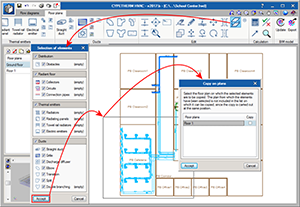
Copy on another floor plan
Using the “Copy on another floor plan” button, users can select elements of the installation to then copy them to another floor.
Arquimedes
Organise decomposition of job items by nature
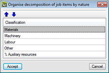
The dialogue “Organise decomposition of job items by nature” (Tree > Reconstruct tree > Organise decomposition of job items by nature > Accept button) has been implemented, which allows users to arrange the decomposition lines of all the job units. In this dialogue, users can change the order of the nature of the decomposition (materials, machinery, labour...). The concepts of each nature will always be arranged in alphabetical order.
The order in which they appear in the new dialogue each time it is opened is always that established in the “Classification by nature” dialogue box (Show > Concept classification > Classification by nature) regardless of whether it has been changed previously. Whilst the new dialogue box is not accepted (Organise decomposition of job items by nature), the order of the decomposition will not vary.
The order will not affect the decomposition of the job units that have partial payments.
Please bear in mind, that due to the arrangement, job units which contain percentage-type concepts (auxiliary resources, complementary direct expenses...) could vary in price because these concepts affect all or some of the concepts situated above them and never those situated below.
Bill of quantities of Revit models
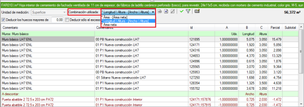
Part to deduct from quantities
New predefined combinations have been created to incorporate the part to be deducted in a quantity. The part to deduct is identified using a hyphen and quotation marks.
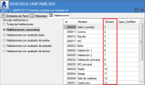
“Number” column in the “Job item assignment and quantity extraction” dialogue box
The “Number” column has been included in the “Rooms” tab of the “Job item assignment and quantity extraction” dialogue box when quantities are linked to specific rooms. This new column allows users to identify the assigned room number in the Revit model.
Filter order memorisation in quantities
The order of filters defined in quantities to restrict elements is memorised. This order is available by accessing the filter editing option.
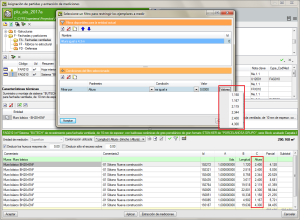
“Values” button added in the “Select a filter to limit the elements to be measured” dialogue box
The “Values” button has been added in the “Select a filter to limit the elements to be measured” to allow users to view all the available values for the selected parameter.
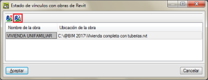
“Change location of Revit model” button
A new button: “Change the location of the Revit model” has been included in the “Link status with Revit jobs” dialogue box (File > Connection with Revit), so users can re-link the Revit project with a bill of quantities of Arquimedes in case the Revit project is duplicated or its location is modified.
Return to the 2017 version download area
Tel. USA (+1) 202 569 8902 // UK (+44) 20 3608 1448 // Spain (+34) 965 922 550 - Fax (+34) 965 124 950